
Universal Transmitters for Smart MODBUS RTU Sensors
3TX-RTU UNIVERSAL SMART 4-20mA TRANSMITTER for HiQDT MODBUS RTU pH, ORP, Dissolved Oxygen (D.O.), Ion Selective (ISE) & Conductivity (EC) Smart Digital Sensor
- Provides local display & isolated, scalable & reversible 0-20mA or 4-20mA output of measured parameter from mating smart digital HiQDT MODBUS RTU sensor
3TX-RTU has 3 digit display & 6 LEDs to setup & display values. ‘Mode’ is used to navigate. Programming done by 3 keys. ‘Mode’ toggles & ‘Up’ or ‘Down’ used to scroll & select. Setup Parameters entered via ‘Mode’. Values changed using ‘Up’ or ‘Down’. The 3TX-RTU automatically selects & illuminates LED based upon the type of sensor which is connected.
If softwarelock (P01) “On” no changes can be made. Set P01 to “Off “ to allow for changes to scaling & configuration. If keys are not used for several minutes then software lock resets back “On”.
- Display current mA output based upon current sensor reading & scaling setup
- Galvanic isolation between sensor input, power & analog output (3000V rating)
- Output scalable down to 2% of the full range input of mating sensor
- Universal software automatically detects measurement type of mating sensor & loads all necessary associated parameters without any user action required
- Temperature & Absolute mV can be display for pH/ORP/ISE/DO sensors. Temperature & raw conductivity can be displayed for conductivity sensors.
- Customized user-defined default settings can be programmed without charge
- Provides isolated 9VDC power & RS-485 serial port for smart HiQDT sensors
- Smart digital HiQDT MODBUS RTU sensors store all calibrations, time since calibration performed, dispatch date, time used in field in non-volatile EEPROM memory for installation portability for seamless plug and play hot-swap in field
- Calibration of sensors done by handheld communicator or Windows software.
- Notifies when connected sensor needs recalibration (user adjustable threshold)
- Cable lengths up to 610 meters (2,000 feet) using rugged NEMA 6P & IP67 rated quick disconnect waterproof & corrosion-resistant snap connector terminations.
- Supported Data Ranges for Mating Smart digital HiQDT MODBUS RTU Sensors:
- pH: -2.000 to +16.000 (actual range is always limited by sensor specs)
- ORP: ±1000.0mV Standard Style or ±2000.0mV Wide Range Style
- Dissolved Oxygen (D.O.): 0.00-150.00 ppm | 0.0-1,500.0 % Saturation
- Ion Selective (ISE): 0.01-9.99 / 10.0-99.9 / 100-999 for ppm ranges & 1.00-9.99 / 10.0-99.9 / 100-99 kilo-ppm ranges (see ppm equivalents below) 1,000-9,990 / 10,000-99,900 / 100,000-999,000 ppm
- Conductivity (EC): 0.01-9.99/10.0-99.9/100-999 for μS/cm ranges and 1.00-9.99 / 10.0-99.9 / 100-999 for mS/cm ranges. The computed units salinity (PSU), TDS & resistivity (MΩ) supported for display & output
- Temperature: -40.0 to +210.0 °C for all sensor types (display values only)
Touchscreen Controller for Smart Digital RS-485 MODBUS RTU RHINO pH, ORP, Conductivity, ISE & D.O. Sensors
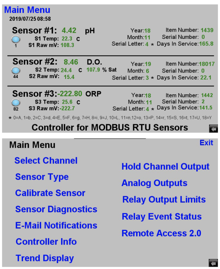
Default home screen shows live process & temperature values for all connected Digital sensors & raw absolute mV values for all channels in controller configuration. If the commissioning steps as detailed in page 5 of this manual were successful completed, then sensors added will be shown in this home screen along together with corresponding node address in use for each channel.
If for any reason any of the channels that was setup does not display correctly it is possible to use the “RHINO Windows Datalogging & Graphing Windows Software for 3TX Transmitters with MODBUS Output” to troubleshoot the Digital MODBUS sensor configuration. In this case you would temporarily disconnect the D+ & D- input leads to the HMI and temporarily redirect the output to this Windows software (contact factory for assistance). Please refer to the separate manual for this software for instructions on how to configure it for use with the Digital sensors for such a purpose.
Main Menu is accessible from the home default display screen as shown on top to the right. Exiting from the main menu will load back the default display screen. After a period of inactvivity you will also get returned back to the home default display screen.
Subsequent portions of manual detail specific sub-menus or screens that are accessible starting from this main menu. If unsure where as specific menu is located please refer to the table of contents on the previous page six (6).